8-bit General Purpose GT MCUs
Design Files
Quick reference to our
design files types.
1 design file
-
Calculators
S08 Battery Calculator
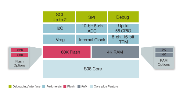
The MC9S08GB family are members of the cost-effective, high-performance S08 general purpose 8-bit microcontrollers. All MCUs in the family use the enhanced S08 core and are available with a variety of modules, memory sizes, memory types and package types.
The S08 family is an extension of the HC08 family, offering extended battery life with maximum performance down to 1.8-volt, high-performance flash and innovative development support.
8-bit General Purpose GT MCUs
Quick reference to our documentation types.
1-10 of 71 documents
Compact List
1 design file
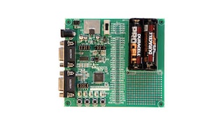
2 hardware offerings

Quick reference to our software types.
1-5 of 12 software files
Note: For better experience, software downloads are recommended on desktop.