8-bit EEPROM Emulation LJ and LK MCUs
Design Files
Receive the full breakdown. See the product footprint and more in the eCad file.
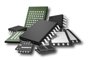
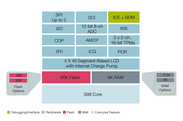
The S08LC microcontroller expands Our 8-bit portfolio by offering an integrated LCD controller with the low-power and feature-rich capabilities of the S08 family. It is the first LCD S08 8-bit microcontroller for battery-powered and handheld applications. The S08LC is a flash-based device with enhanced EEPROM emulation, eliminating the need for off-chip EEPROM, saving both board space and cost.
The S08LC is specifically crafted to provide high segment count that is easy on the batteries. A larger segment display of up to 160 segments offers total flexibility with a graphical display and sufficient memory to act as application and LCD controller without the added cost of a dot matrix or chip-on-glass,? fulfilling the need for a broad spectrum of applications with displays.
8-bit EEPROM Emulation LJ and LK MCUs
|
|
|
|
|
|
|
|---|---|---|---|---|---|
|
|
|
|
|
|
|
|
|
|
|
|
|
|
|
|
|
|
|
|
|
|
|
|
|
|
|
|
|
|
|
|
|
|
|
|
|
|
|
|
|
|
|
|
|
|
|
|
|
|
|
|
|
|
|
|
|
|
|
|
|
|
|
|
|
|
|
|
|
|
Quick reference to our documentation types.
1-10 of 28 documents
Compact List
Receive the full breakdown. See the product footprint and more in the eCad file.
4 hardware offerings
Additional hardware available. View our featured partner solutions.
Quick reference to our software types.
1-5 of 11 software files
Additional software available. View our featured partner solutions.
Note: For better experience, software downloads are recommended on desktop.
To get further assistance directly from NXP, please see our Engineering Services.
2 engineering services

To find additional partner offerings that support this product, visit our Partner Marketplace.