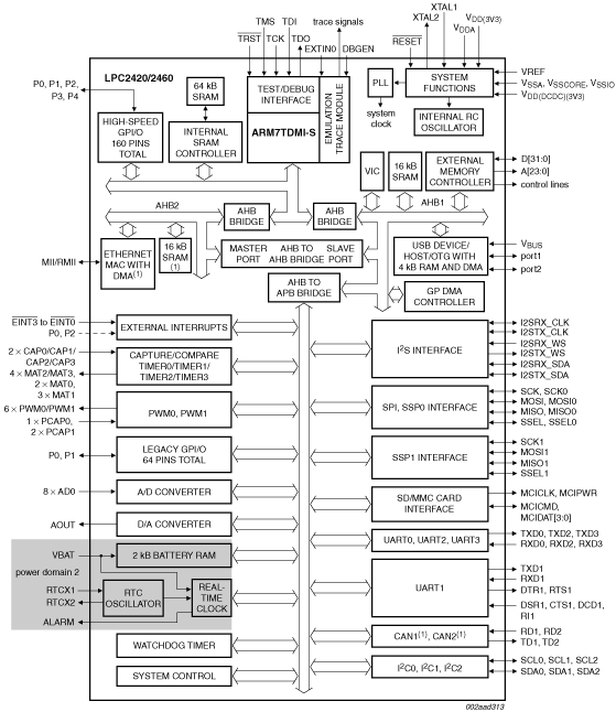
Flashless 16-bit/32-bit microcontroller; Ethernet, CAN, ISP/IAP, USB 2.0 device/host/OTG, external memory interface

  • This page contains information on a product that is not recommended for new designs.

See product image

Product Details

Block Diagram

Block diagram: LPC2420FBD208, LPC2460FBD208, LPC2460FET208

Features

  • Arm7TDMI-S processor, running at up to 72 MHz.
  • 82/98 kB on-chip SRAM includes:
    • 64 kB of SRAM on the Arm® local bus for high performance CPU access.
    • 16 kB SRAM for Ethernet interface. Can also be used as general purpose SRAM. (LPC2460 only)
    • 16 kB SRAM for general purpose DMA use also accessible by the USB.
    • 2 kB SRAM data storage powered from the Real-Time Clock (RTC) power domain.
  • Dual Advanced High-performance Bus (AHB) system allows simultaneous Ethernet DMA, and USB DMA with no contention (LPC2460 only).
  • EMC provides support for asynchronous static memory devices such as RAM, ROM and flash, as well as dynamic memories such as single data rate SDRAM.
  • Advanced Vectored Interrupt Controller (VIC), supporting up to 32 vectored interrupts.
  • General Purpose DMA controller (GPDMA) on AHB that can be used with the SSP, I²S, and SD/MMC interface as well as for memory-to-memory transfers.
  • Serial Interfaces:
    • Ethernet MAC with MII/RMII interface and associated DMA controller (LPC2460 only). These functions reside on an independent AHB.
    • USB 2.0 full-speed dual port device/host/OTG controller with on-chip PHY and associated DMA controller.
    • Four UARTs with fractional baud rate generation, one with modem control I/O, one with IrDA support, all with FIFO.
    • CAN controller with two channels (LPC2460 only).
    • SPI controller.
    • Two SSP controllers, with FIFO and multi-protocol capabilities. One is an alternate for the SPI port, sharing its interrupt. SSPs can be used with the GPDMA controller.
    • Three I²C-bus interfaces (one with open-drain and two with standard port pins).
    • I²S (Inter-IC Sound) interface for digital audio input or output. It can be used with the GPDMA.
  • Other peripherals:
    • SD/MMC memory card interface.
    • 160 General purpose I/O pins with configurable pull-up/down resistors.
    • 10-bit ADC with input multiplexing among 8 pins.
    • 10-bit DAC.
    • Four general purpose timers/counters with 8 capture inputs and 10 compare outputs. Each timer block has an external count input.
    • Two PWM/timer blocks with support for three-phase motor control. Each PWM has an external count inputs.
    • RTC with separate power domain. Clock source can be the RTC oscillator or the APB clock.
    • 2 kB SRAM powered from the RTC power pin, allowing data to be stored when the rest of the chip is powered off.
    • WatchDog Timer (WDT). The WDT can be clocked from the internal RC oscillator, the RTC oscillator, or the APB clock.
  • Standard Arm test/debug interface for compatibility with existing tools.
  • Emulation trace module supports real-time trace.
  • Single 3.3 V power supply (3.0 V to 3.6 V).
  • Four reduced power modes: idle, sleep, power-down, and deep power-down.
  • Four external interrupt inputs configurable as edge/level sensitive. All pins on port 0 and port 2 can be used as edge sensitive interrupt sources.
  • Processor wake-up from Power-down mode via any interrupt able to operate during Power-down mode (includes external interrupts, RTC interrupt, USB activity, port 0/2 pin interrupt, Ethernet wake-up interrupt (LPC2460 only), CAN bus activity (LPC2460 only)).
  • Two independent power domains allow fine tuning of power consumption based on needed features.
  • Each peripheral has its own clock divider for further power saving. These dividers help reduce active power by 20 % to 30 %.
  • Brownout detect with separate thresholds for interrupt and forced reset.
  • On-chip power-on reset.
  • On-chip crystal oscillator with an operating range of 1 MHz to 25 MHz.
  • 4 MHz internal RC oscillator trimmed to 1 % accuracy that can optionally be used as the system clock. When used as the CPU clock, does not allow CAN and USB to run.
  • On-chip PLL allows CPU operation up to the maximum CPU rate without the need for a high frequency crystal. May be run from the main oscillator, the internal RC oscillator, or the RTC oscillator.
  • Boundary scan for simplified board testing.
  • Versatile pin function selections allow more possibilities for using on-chip peripheral functions.

Target Applications

  • Industrial control
  • Medical systems
  • Protocol converter
  • Communications

Buy/Parametrics


Documentation

Quick reference to our documentation types.

1-10 of 20 documents

Compact List

Application Note (12)
Brochure (2)
Data Sheet (1)
Errata (1)
Package Information (1)
Packing Information (1)
Supporting Information (1)
User Guide (1)

Design Files

Quick reference to our design files types.

1 design file

Software

Quick reference to our software types.

2 software files

Note: For better experience, software downloads are recommended on desktop.

Support

What do you need help with?