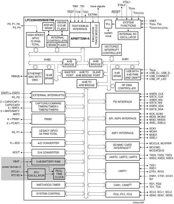
Arm7 with 512 kB flash, 58 kB SRAM, Ethernet, USB 2.0 Device, CAN, SD/MMC, and 10-bit ADC

  • This page contains information on a product that is not recommended for new designs.

See product image

Product Details

Block Diagram

Block diagram: LPC2364FBD100, LPC2364FET100, LPC2364HBD100, LPC2365FBD100, LPC2366FBD100, LPC2367FBD100, LPC2368FBD100, LPC2368FET100

Features

  • Arm7TDMI-S processor, running at up to 72 MHz
  • Up to 512 kB on-chip flash program memory with In-System Programming (ISP)
  • 32 kB of SRAM on the Arm local bus for high performance CPU access
  • 8 kB SRAM for general purpose DMA use also accessible by the USB
  • 16 kB SRAM for Ethernet interface. Can also be used as general purpose SRAM
  • Dual Advanced High-performance Bus (AHB) system
  • Advanced Vectored Interrupt Controller (VIC)
  • General Purpose DMA controller (GPDMA) on AHB
  • Ethernet MAC with associated DMA controller
  • Four UARTs with fractional baud rate generation
  • USB 2.0 full-speed device with on-chip PHY
  • CAN controller with two channels
  • SPI controller
  • Two SSP controllers, with FIFO and multi-protocol capabilities
  • Three I2C-bus interfaces
  • I2S (Inter-IC Sound) interface for digital audio input or output
  • SD/MMC memory card interface
  • 70 general purpose I/O pins with configurable pull-up/down resistors
  • 10-bit ADC with input multiplexing among 6 pins
  • 10-bit DAC
  • Four general purpose timers/counters with a total of 8 capture inputs
  • One PWM/timer block with support for three-phase motor control
  • Real-Time Clock (RTC)
  • 2 kB SRAM powered from the RTC power pin
  • WatchDog Timer (WDT).
  • Standard Arm test/debug interface for compatibility with existing tools
  • Emulation trace module supports real-time trace
  • Single 3.3 V power supply (3.0 V to 3.6 V)
  • Four reduced power modes: idle, sleep, power-down, and deep power-down
  • Four external interrupt inputs configurable as edge/level sensitive
  • Processor wake-up from Power-down mode via any interrupt
  • Two independent power domains allow fine tuning of power consumption
  • Each peripheral has its own clock divider for further power saving
  • Brownout detect with separate thresholds for interrupt and forced reset
  • On-chip power-on reset
  • On-chip crystal oscillator with an operating range of 1 MHz to 24 MHz
  • 4 MHz internal RC oscillator trimmed to 1 % accuracy
  • On-chip PLL

Target Applications

  • Industrial control
  • Medical systems
  • Protocol converter
  • Communications

Buy/Parametrics


Documentation

Quick reference to our documentation types.

1-10 of 16 documents

Compact List

Application Note (9)
Brochure (2)
Data Sheet (1)
Errata (1)
Package Information (1)
Supporting Information (1)
User Guide (1)

Design Files

Quick reference to our design files types.

2 design files

Software

Quick reference to our software types.

2 software files

Note: For better experience, software downloads are recommended on desktop.

Support

What do you need help with?