


Safe Assure® (Functional Safety)
When it comes to functional safety, NXP stands for quality and reliability. Our SafeAssure program simplifies system-level safety requirements in accordance with ISO 26262.
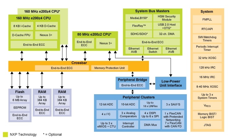
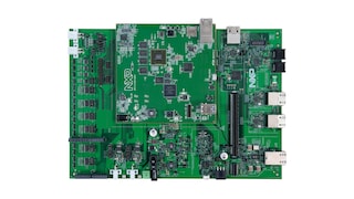
The MPC574xB/C/G family of MCUs (eg. MPC5746C, MPC5748G) provides a highly integrated, safe and secure single-chip solution for next-generation central body control, gateway and industrial applications.
Choose a diagram:
When it comes to functional safety, NXP stands for quality and reliability. Our SafeAssure program simplifies system-level safety requirements in accordance with ISO 26262.
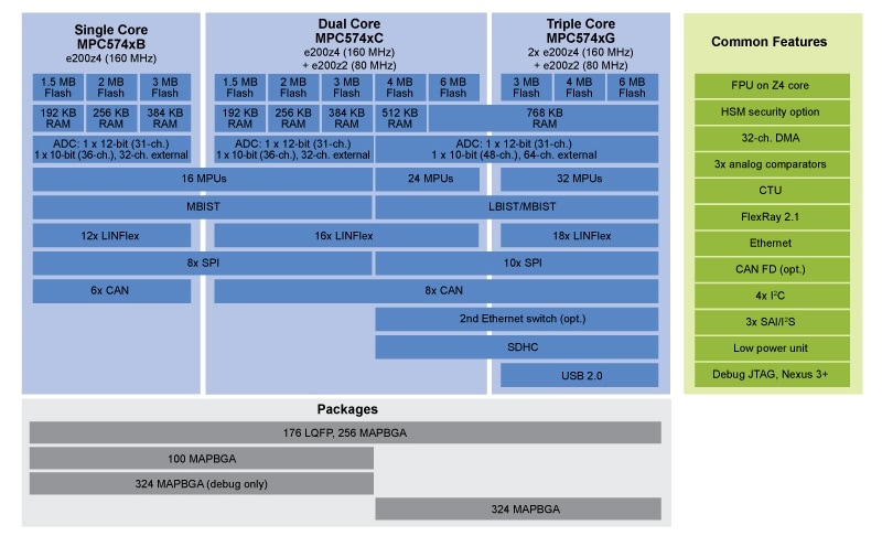
| Single Core MPC574xB e200z4 (160MHz) |
Dual Core MPC574xC e200z4 (160MHz) + e200z2 (80MHz) |
Triple Core MPC574xG 2x e200z4 (160MHz) + e200z2 (80MHz) |
||||||||
|---|---|---|---|---|---|---|---|---|---|---|
| 1.5MB Flash |
2MB Flash |
3MB Flash |
1.5MB Flash |
2MB Flash |
3MB Flash |
4MB Flash |
6MB Flash |
3MB Flash |
4MB Flash |
6MB Flash |
| 192kB RAM |
256kB RAM |
384kB RAM |
192kB RAM |
256kB RAM |
384kB RAM |
512kB RAM |
768kB RAM |
|||
| ADC: 1x12bit (31ch) 1x10bit (36ch), 32ch external |
ADC: 1x12bit (31ch) 1x10bit (36ch), 32ch external |
ADC: 1x12bit (31ch) 1x10bit (48ch), 64ch external |
||||||||
| 16 MPUs | 24 MPUs | 32 MPUs | ||||||||
| MBIST | LBIST / MBIST | |||||||||
| 12x LINFlex | 16x LINFlex | 18x LINFlex | ||||||||
| 8x SPI | 10x SPI | |||||||||
| 6x CAN | 8x CAN | |||||||||
| 2nd Ethernet switch (opt.) | ||||||||||
| SDHC | ||||||||||
| USB 2.0 | ||||||||||
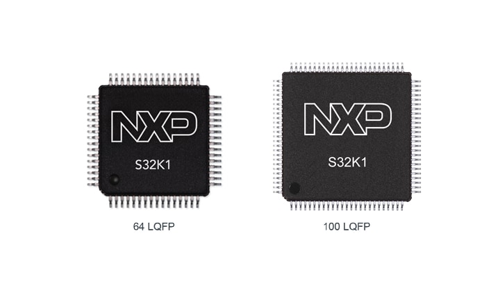
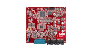
S32K1 Microcontrollers for Automotive General Purpose
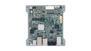
Ultra-Reliable MPC564xB-C MCU for Automotive and Industrial Control Applications
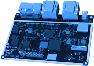
Ultra-Reliable MPC56xB MCU for Automotive and Industrial General Purpose
|
|
|
|
|
|
|
|---|---|---|---|---|---|
|
|
|
|
|
|
|
|
|
|
|
|
|
|
|
|
|
|
|
|
|
|
|
|
|
|
|
|
|
|
|
|
|
|
|
|
|
|
|
|
|
|
|
|
|
|
|
|
|
|
|
|
|
|
|
|
|
|
|
|
|
|
|
|
|
|
|
|
|
|
Quick reference to our documentation types.
1-10 of 49 documents
Compact List
2 design files
1-5 of 12 hardware offerings

Additional hardware available. View our featured partner solutions.
Quick reference to our software types.
1-5 of 20 software files
Additional software available. View our featured partner solutions.
Note: For better experience, software downloads are recommended on desktop.
To get further assistance directly from NXP, please see our Engineering Services.
1-5 of 14 engineering services


To find additional partner offerings that support this product, visit our Partner Marketplace.
-01.svg?imwidth=300)


