Application Note (5)
Data Sheet (1)
Errata (1)
-
Errata sheet LPC43S50, LPC43S30, LPC43S20[ES_LPC43SX0]
Fact Sheet (1)
-
LPC43Sxx Series of MCUs - Fact Sheet[LPC43SXXLF]
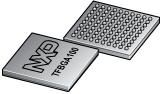
The LPC43S70FET100 is a Arm Cortex-M4 based microcontroller for embedded applications which includes an Arm Cortex-M0 coprocessor and an Arm Cortex-M0 subsystem for managing peripherals, 282 kB of SRAM, advanced configurable peripherals such as the State Configurable Timer (SCTimer/PWM) and the Serial General Purpose I/O (SGPIO) interface, security features with AES engine, two High-speed USB controllers, Ethernet, an external memory controller, and multiple digital and analog peripherals including a high-speed 12-bit ADC. The LPC43S70FET100 operates at CPU frequencies of up to 204 MHz.
The Arm Cortex-M4 is a 32-bit core that offers system enhancements such as low power consumption, enhanced debug features, and a high level of support block integration. The Arm Cortex-M4 CPU incorporates a 3-stage pipeline, uses a Harvard architecture with separate local instruction and data buses as well as a third bus for peripherals, and includes an internal prefetch unit that supports speculative branching. The Arm Cortex-M4 supports single-cycle digital signal processing and SIMD instructions. A hardware floating-point unit is integrated in the core. The Arm Cortex-M4 with floating-point unit is often referred to as M4F.
The LPC43S70FET100 includes an application Arm Cortex-M0 coprocessor and a second Arm Cortex-M0 subsystem for managing the SGPIO and SPI peripherals. The Arm Cortex-M0 core is an energy-efficient and easy-to-use 32-bit core which is code- and tool-compatible with the Cortex-M4 core. Both Cortex-M0 cores offer up to 204 MHz performance with a simple instruction set and reduced code size. The Cortex-M0 does not support hardware multiply.
|
|
|
|
|
|
|
|---|---|---|---|---|---|
|
|
|
|
|
|
|
|
|
|
|
|
|
|
|
|
|
|
|
|
|
|
|
|
|
|
|
|
|
|
|
|
|
|
|
|
|
|
|
|
|
|
|
|
|
|
|
|
|
|
|
|
|
|
|
|
|
|
|
|
|
|
|
|
|
|
|
|
|
|
Quick reference to our documentation types.
1-10 of 12 documents
Compact List
2 design files
Receive the full breakdown. See the product footprint and more in the eCad file.
1-5 of 8 hardware offerings
Additional hardware available. View our featured partner solutions.
Quick reference to our software types.
5 software files
Additional software available. View our featured partner solutions.
Note: For better experience, software downloads are recommended on desktop.
To get further assistance directly from NXP, please see our Engineering Services.
5 engineering services


To find additional partner offerings that support this product, visit our Partner Marketplace.
1-5 of 10 trainings