Getting Started with the P3A1604UK-ARD Evaluation Board
Contents of this document
-
Out of the Box
-
Get to Know the Hardware
-
Configure Hardware
Sign in to save your progress. Don't have an account? Create one.
Purchase your P3A1604UK-ARD
1. Out of the Box
The NXP analog product development boards provide an easy-to-use platform for evaluating NXP products. The boards support a range of analog, mixed-signal and power solutions. They incorporate monolithic integrated circuits and system-in-package devices that use proven high-volume technology. NXP products offer longer battery life, a smaller form factor, reduced component counts, lower cost and improved performance in powering state-of-the-art systems.
This page will guide you through the process of setting up and using the P3A1604UK-ARD board.
1.1 Kit Contents and Packing List
The kit contents include:
- Assembled and tested evaluation board in an antistatic bag
- Quick Start Guide
1.2 Software
Installing software is necessary to work with this evaluation board. All listed software is available on the evaluation board's information page at P3A1604 or from the provided link.
2. Get to Know the Hardware
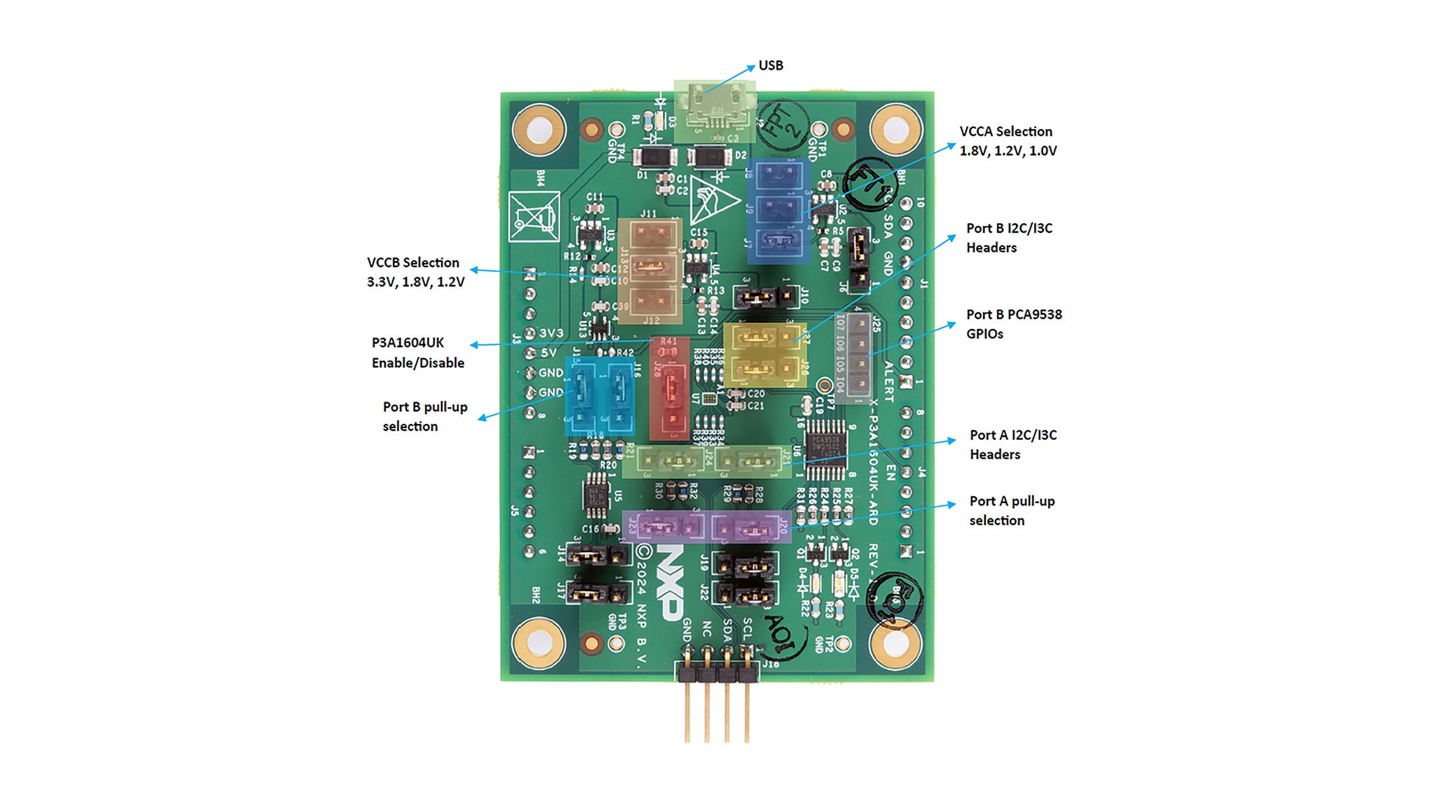
As default, P3A1604UK Port A is configured to operate at 1.8 V while Port B is configured to operate at 3.3 V via jumper settings shown in Table 1. Port A I²C/I3C interface is available at J21 and J24, while Port B I²C/I3C interface is available on J26 and J27.
Port A signals are routed to the Arduino® header (J1) and MCU/Aardvark header (J18) allowing for easy connection to a I²C/I3C controller (MCU).
Port B signals are connected to one on-board 8-bit I²C GPIO expander (PCA9538PW), and one I3C temperature sensor (P3T1750DP). The factory default I²C/I3C addresses for these device are listed in Table 2. The user can also connect their own I²C/I3C target devices to the Port B I²C/I3C interface headers (J26, J27).
GPIO0 and GPIO1 on the PCA9538PW are connected to a pair of LEDs (blue and red). The user can turn on, turn off, or blink the LED by communicating with the PCA9538PW via I²C.
P3A1604UK can be enabled/disabled via J28. It is enabled by default.
P3A1604UK-ARD evaluation board is powered via a USB micro-B connector, J2. There are on-board LDOs to convert 5 V from the micro-B connector to other power rails to provide power to VCCA, VCCB other components on the board. VCCA can be configured through J7, J8, J9. VCCB can be configured through J11, J12, J13.
The P3A1604UK-ARD evaluation board is designed to be mated and controlled by a MCU board with standard Arduino® headers. The P3A1604UK is then powered by the available 5 V rail from the MCU board. Table 3 lists all interface signals the MCU needs to communicate with the P3A1604UK-ARD.

2.1 Board Features
- P3A1604UK-ARD evaluation board is powered via a USB micro-B connector. There are on-board LDOs to convert 5 V from the micro-B connector to other power rails to provide power to VCCA, VCCB other components on the board
- The P3A1604UK-ARD evaluation board is designed to be mated and controlled by an MCU board with standard Arduino® headers. The P3A1604UK is then powered by the available 5 V rail from the MCU board
2.2 Board Description
The P3A1604UK is a quad-bidirectional voltage level translator with auto direction sensing, that enables bidirectional voltage level translation. It includes a reference supply VCCA for port A and VCCB for port B. The supply voltage of VCCA and VCCB is between 0.72 V to 3.63 V. Pins A1 to A4 are referenced to VCCA, pins B1 to B4 are referenced to VCCB. Pin OE is used as the device enable input and is referenced to VCCA.
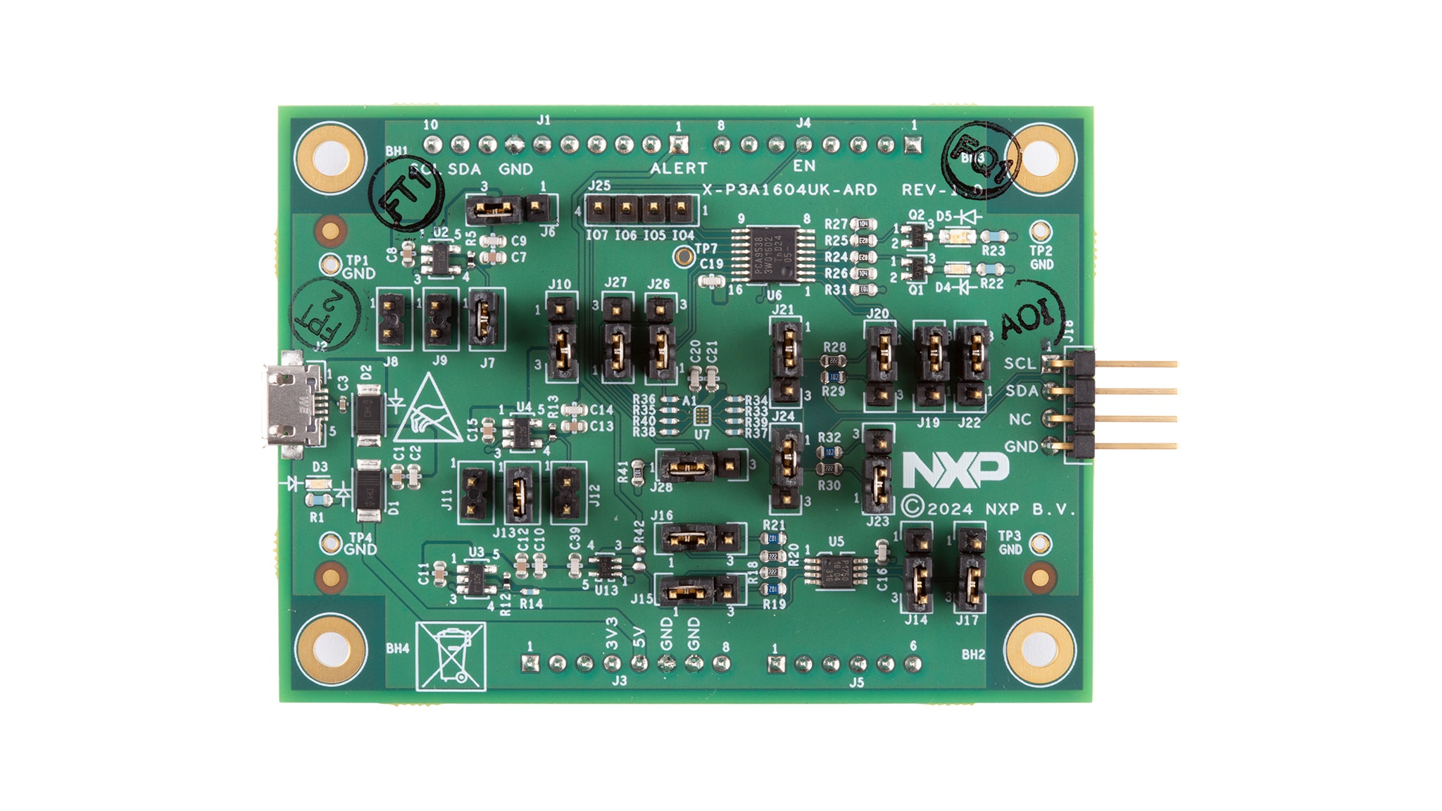
P3A1604UK can be used for both open-drain and push-pull application which allows for I3C bus and other applications like I²C-bus, SMBus and SPI protocols. Refer to the following figure to find the location of connectors and jumpers on the evaluation board.
The schematic, board layout and bill of materials for the P3A1604UK-ARD evaluation board are available at P3A1604.
3. Configure Hardware
3.1 Configure Hardware
- Unpack the board and power it with the micro-B USB cable
- Connect a 1.8 V I3C controller to Port A via
J1(Arduino) orJ18(MCU/Aardvark). See schematic for wiring connection. By default, both port A has on-board 2.2 K pull-ups. If the pull-ups are already present on the I3C controller board, then the on-board pull-ups can be disabled viaJ20andJ23(see Table 1) - 1-2:
VCCAprovided externally - 2-3:
VCCAconnected to LDO output - 1-2:
VCCAprovided externally - 2-3:
VCCAconnected to LDO output - 1-2: P3T1750
A0connect toVCCB - 2-3: P3T1750
A0connect toGnd - 1-2: P3T1750
A1connect toVCCB - 2-3: P3T1750
A1connect toGnd - 1-2: Port B 2.2 k pull-ups
- 2-3: Port B 1 k pull-ups
- 1-2: PCA9538
A0connect toVCCB - 2-3: PCA9538
A0connect toGnd - 1-2: PCA9538
A1connect toVCCB - 2-3: PCA9538
A1connect toGnd - 1-2: Port A 2.2 k pull-ups
- 2-3: Port A 1 k pull-ups
- 1-2: Connect Host SCL to pin
A1of P3A1604UK - 2-3: Connect Host SCL to pin
A3of P3A1604UK - 1-2: Connect Host SDA to pin
A2of P3A1604UK - 2-3: Connect Host SDA to pin
A4of P3A1604UK - 1-2: Connect Device SCL to pin
B1of P3A1604UK - 2-3: Connect Device SCL to pin
B3of P3A1604UK - 1-2: Connect Device SCL to pin
B2of P3A1604UK - 2-3: Connect Device SCL to pin
B4of P3A1604UK - 1-2: Enable P3A1604UK
- 2-3: Disable P3A1604UK
- The I3C controller then can communicate with the 8-bit GPIO PCA9538PW via I²C, or the temperature senser P3T1750DP via I3C/I²C. These devices are located at different I²C/I3C addresses, see Table 2 for their default factory addresses
- The P3A1604UK-ARD evaluation board is designed to be mated and controlled by an MCU board equipped with standard Arduino headers. There are four headers used for this purpose:
J1,J3,J4andJ5
| Jumper | Default Setting | Comment |
|---|---|---|
J1, J3, J4, J5 |
NA | Arduino header |
J2 |
NA | USB micro-B connector |
J6 |
2-3 |
|
J7 |
1-2 | 1-2: VCCA = 1.8 V (J8 and J9 open) |
J8 |
Open | 1-2: VCCA = 1.2 V (J7 and J9 open) |
J9 |
Open | 1-2: VCCA = 1.0 V (J7 and J8 open) |
J10 |
2-3 |
|
J11 |
Open | 1-2: VCCB = 1.2 V (J12 and J13 open) |
J12 |
Open | 1-2: VCCB = 1.8 V (J11 and J13 open) |
J13 |
1-2 | 1-2: VCCB = 3.3 V (J11 and J12 open) |
J14 |
2-3 |
|
J17 |
2-3 |
|
J15, J16 |
1-2 |
|
J18 |
NA | MCU/Aardvark header |
J19 |
2-3 |
|
J22 |
2-3 |
|
J20, J23 |
1-2 |
|
J21 |
1-2 |
|
J24 |
1-2 |
|
J25 |
NA | Port B GPIOs header |
J26 |
1-2 |
|
J27 |
1-2 |
|
J28 |
1-2 |
|
| Type | Device | Address |
|---|---|---|
| I²C | PCA9538PW | U6 - Adr. 0xE0 |
| I3C | P3T1750DP | U5 - Adr. 0x90 |
| Signal | Header | Pin | Comment |
|---|---|---|---|
| MCU_ALERT | J1 |
1 | Interrupt output from P3T1750DP |
| MCU_I²C_SCL | J1 |
10 | MCU SCL |
| MCU_I²C_SDA | J1 |
9 | MCU SDA |
| 5V0_uC | J3 |
5 | 5 V supply from the MCU board |
| 3V3_uC | J3 |
4 | 3V3 supply from the MCU board. Not used |
| MCU_EN | J4 |
5 | P3A1604UK Enable control |
Design Resources
Board Information
Additional References
In addition to our P3A1604UK-ARD evaluation board, you may also want to visit: