Getting Started with the TJA1445A-EVB
Contents of this document
-
Out of the Box
-
Get Hardware
-
Configure Hardware
Sign in to save your progress. Don't have an account? Create one.
Purchase your TJA1445A CAN FD PN - IO Evaluation Board
1. Out of the Box
The NXP analog product development boards provide an easy-to-use platform for evaluating NXP products. The boards support a range of analog, mixed-signal and power solutions. They incorporate monolithic integrated circuits and system-in-package devices that use proven high-volume technology. NXP products offer longer battery life, a smaller form factor, reduced component counts, lower cost, and improved performance in powering state-of-the-art systems. This page will guide you through the process of setting up and using the TJA1445A-EVB board.
1.1 Kit Contents and Packing List
The kit contents include:
- Assembled and tested TJA1445A-EVB evaluation board in an antistatic bag
1.2 Additional Hardware
In addition to the kit contents, the following hardware are been needed when working with this board.
- A 12 V power supply
- A windows PC and a USB cable to run the FlexGUI application
- S32K148-Q176 MCU evaluation board, available at NXP
1.3 Software
The dedicated FlexGUI software package used to communicate with TJA1445A-EVB must be downloaded and installed, as described in theTJA1445A-EVB user manual (UM12257). The software package contains the FlexGUI installer and FlexGUI firmware for the S32K148-Q176 microcontroller board. The software and associated documentation is available on the TJA1445A-EVB.
2. Get Hardware
The TJA1445A-EVB board was designed to facilitate the testing and evaluation of TJA14xx product features in a variety of microcontroller I/O interface environments. The TJA14xx-EVB family consists of the following evaluation boards:
- TJA1445A-EVB
- TJA1445A-EVB
- TJA1465A-EVB
- TJA1465B-EVB
- TJA1466B-EVB
- TJA1466C-EVB
When a TJA1445B device is being evaluated, take a TJA1465B-EVB and replace the TJA1465B with a TJA1445B. When a TJA1446C device is being evaluated, take a TJA1466C-EVB and replace the TJA1466C with a TJA1446C. The TJA1446A and TJA1466A would need a 1.8 V VIO supply, which is not supported by the S32K148EVB.
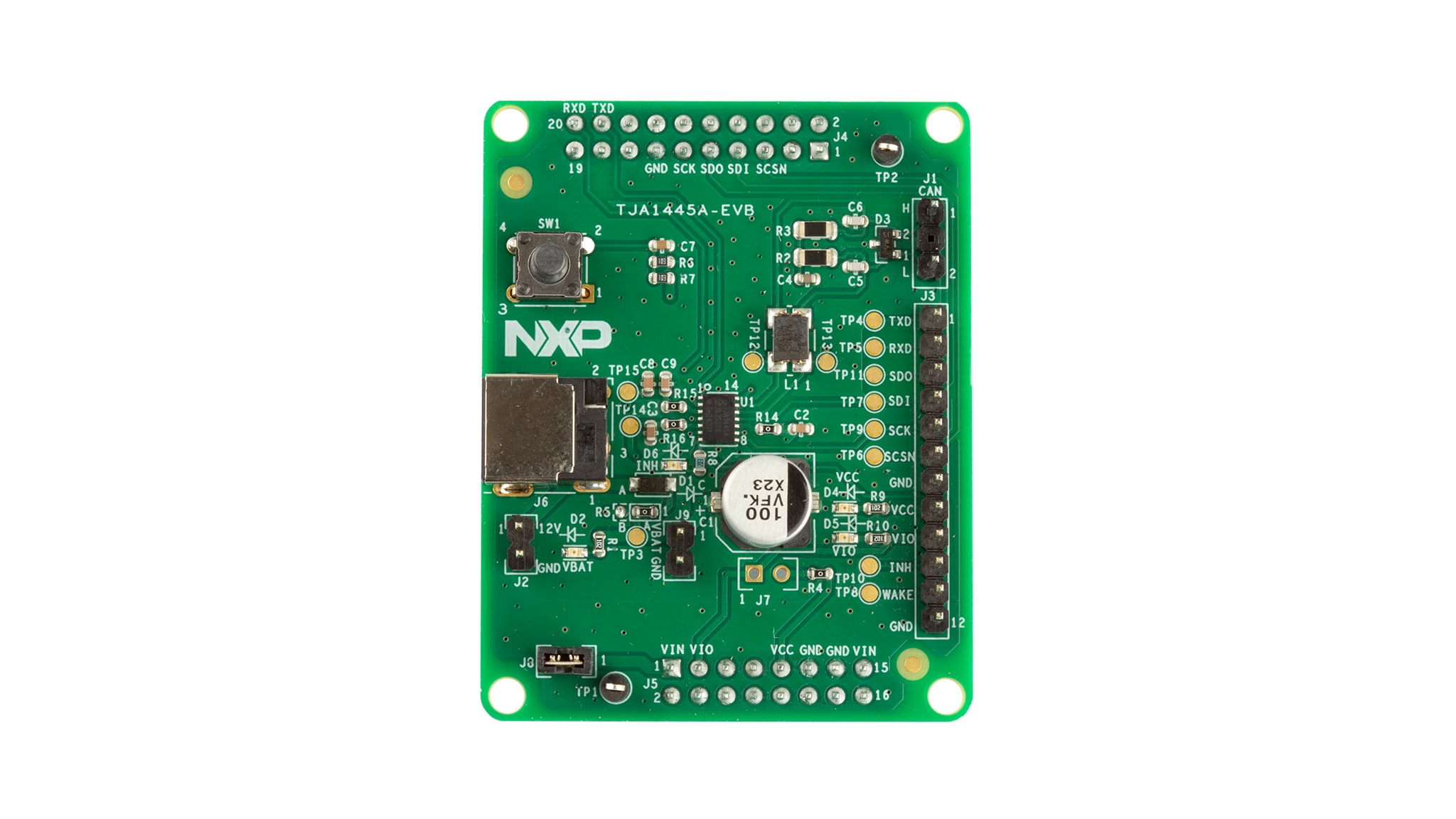
2.1 Board Description
Top and bottom views of the TJA1466B-EVB are shown are in Figure 1. Board dimensions are 42 mm x 78 mm. Only components needed to support basic functionality are included. The other evaluation boards, incuding TJA1445A-EVB, have a similar layout.
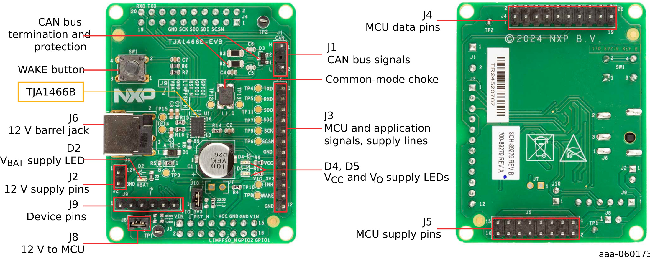
2.2 Board Features
Dimensions: 42 mm x 78 mm
- Board contains CAN bus filter, termination and protection circuitry along with power supply and wake-up circuitry
- LEDs indicate the status of the VBAT, VCC and VIO supplies
- Header rows are provided to connect the the MCU interface and application signals
3. Configure Hardware
The TJA1445A-EVB Configuration GUI software used to communicate with the board via USB must be downloaded and installed from the FlexGUI software page.
3.1 Configuring the Hardware
When the TJA1445A-EVB is used with the S32K148-Q176 microcontroller evaluation board, the microcontroller board can be used as a USB/SPI interface between the TJA1445A-EVB and a PC.
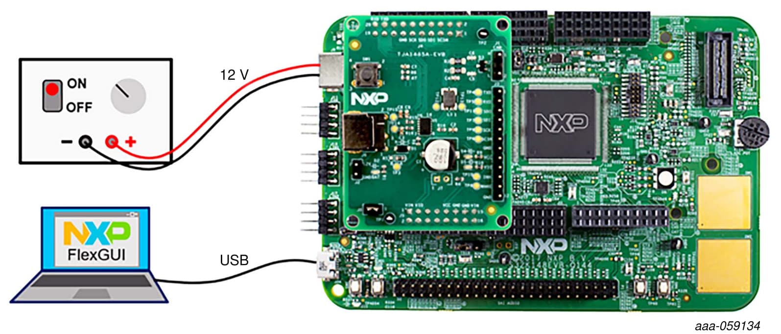
FlexGUI firmware must be installed on the S32K148EVB before connecting the TJA14xx-EVB, as detailed in the user manual. Once the FlexGUI firmware has been installed on the microcontroller board, it is recommended to set the VIO and VCC supply jumpers on as indicated in Table 1. Further information about the jumpers and available voltage levels can be found in the S32K148EVB Getting Started guide.
| Product | J7 (MCU VDD) |
J8 (5 V VCC) |
J18 (3.3 V source) |
|---|---|---|---|
| TJA14x6A (1.8 V VIO) | not supported[1] | - | - |
| TJA14x6B (3.3 V VIO) | 1-2 (3.3 V) | 1-2 | 1-2 (VBAT) |
| TJA14x6C (3.3 V - 5 V VIO) | 1-2 (3.3 V)[2] | 1-2 | 1-2 (VBAT)[3] |
| TJA14x5A/B | 1-2 (3.3 V) | 1-2 | 1-2 (VBAT) |
Once the S32K148EVB board has been configured, the TJA1445A-EVB needs to be connected. See S32K148-Q176 to learn more about the S32K148-Q176 board.
Design Resources
Board Information
Additional Resources
In addition to product pages containing details of our PHY devices, you may also want to visit: